
A mains pressure hot water supply system incorporating an off peak electric thermal store.
Design, Installation & Servicing Instructions
For Gledhill PulsaCoil A-Class Parts and Spares click on the following links: Gledhill PulsaCoil A-Class Parts And Spares
Model Numbers
ISSUE 9: 06-08
Section
DESIGN
Introduction
Technical Data
System Details
INSTALLATION
Site Requirements
Installation
Commissioning
SERVICING
Annual Service
Changing Components
Short Parts List
Fault Finding
ADDENDIX
Addendix A
Addendix B
Addendix C
Addendix D
Terms & Conditions
![]() The code of practice for the installation,
The code of practice for the installation,
commissioning & servicing of central heating systems
Building Regulations and Benchmark Commissioning
The Building Regulations (England & Wales) require that the installation of a heating appliance be notified to the relevant Local Authority Building Control Department. From 1st April 2005 this can be achieved via a Competent Person Self Certification Scheme as an option to notifying the Local Authority directly. Similar arrangements will follow for Scotland and will apply in Northern Ireland from 1st January 06.
CORGI operates a Self Certification Scheme for gas heating appliances.
These arrangements represent a change from the situation whereby compliance with the Building Regulations was accepted if the Benchmark Logbook was completed and this was then left on site with the customer).
With the introduction of a self certification scheme, the Benchmark Logbook is being replaced by a similar document in the form of a commissioning check list and a service interval record is included with all gas appliance manuals. However, the relevant Benchmark Logbook is still being included with all Thermal Storage products and unvented cylinders.
Gledhill fully supports the Benchmark aims to improve the standards of installation and commissioning of central heating systems in the UK and to encourage the regular servicing of all central heating systems to ensure safety and efficiency.
Building Regulations require that the heating installation should comply with the manufacturer’s instructions. It is therefore important that the commissioning check list is completed by the competent installer. This check list only applies to installations in dwellings or some related structures.
The Gledhill PulsaCoil range is a WBS listed product and complies with the WMA Specification for hot water only thermal storage products. The principle was developed originally in conjunction with British Gas. This product is manufactured under an ISO 9001:2000 Quality System audited by BSI.
The Gledhill Group’s first priority is to give a high quality service to our customers.
Quality is built into every Gledhill product and we hope you get satisfactory service from Gledhill.
If not please let us know.
DESIGN
For Gledhill PulsaCoil A-Class Parts and Spares click on the following links: Gledhill PulsaCoil A-Class Parts And Spares
Any water distribution system/installation must comply with the relevant recommendations of the current version of the Regulations and British Standards listed below:-
Building Regulations
Requirements for Electrical Installations
Water Regulations
Manual Handling Operations Regulations
British Standards
BS6700 and BS7671.
A suitably competent trades person must install the PulsaCoil and carry out any subsequent maintenance/repairs. In fact the appliance front cover is secured by 2 screws and this should only be removed by a competent trades person. The manufacturer’s notes must not be taken as overriding statutory obligations.
The PulsaCoil A-Class is not covered by section G3 of the current Building Regulations and is therefore not notifiable to Building Control.
The PulsaCoil A-Class is not intended for use by persons (including children) with reduced physical, sensory or mental capabilities, or lack of experience or knowledge, unless they have been given supervision or instruction concerning use of the appliance by a person responsible for their safety.
Children should be supervised to ensure that they do not play with the appliance.
The information in this manual is provided to assist generally in the selection of equipment. The responsibility for the selection and specification of the equipment must however remain that of the customer and any Designers or Consultants concerned with the design and installation.
Please Note: We do not therefore accept any responsibility for matters of design, selection or specification or for the effectiveness of an installation containing one of our products unless we have been specifically requested to do so.
All goods are sold subject to our Conditions of Sale, which are set out at the rear of this manual.
In the interest of continuously improving the PulsaCoil range, Gledhill Water Storage Ltd reserve the right to modify the product without notice, and in these circumstances this document, which is accurate at the time of printing, should be disregarded. It will however be updated as soon as possible after the change has occurred.
DESIGN
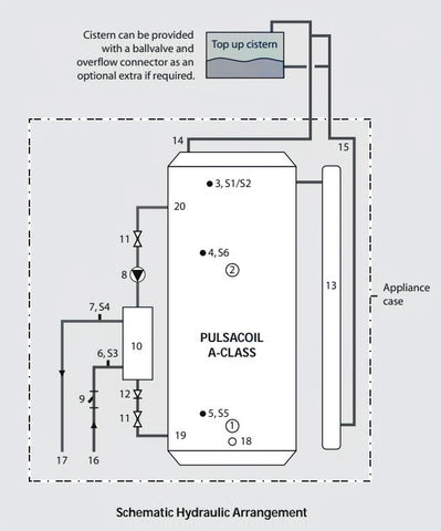
1. Bottom (Off-Peak) immersion heater (1H_1)
2. Top (On-Peak) immersion heater (IH_2)
3. Overheat sensor pocket (Sensor S1/S2)
4. Top/middle sensor pocket (Sensor S6 for IH_2)
5. Bottom sensor pocket (Sensor S5 for IH_1)
6. Cold water inlet sensor, S3
7. DHW outlet sensor, S4
8. Grundfos UPR 15-50 pump
9. Filter & flow regulator
10. Plate heat exchanger
11. Pump isolating valve
12. Non-Return valve
13. Pre-expansion chamber
14. Open vent
15. Cold Feed
16. CW inlet
17. HW outlet
18. Drain
19. Return from PHE to store
20. Flow from store to PHE
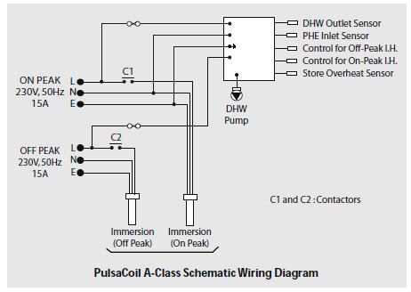
The PulsaCoil A-Class shown schematically above is designed to provide an improved method of supplying mains pressure hot water when used with a suitable off peak electric supply/tariff.
An important feature of the concept is that hot water can be supplied directly from the mains at conventional flow rates without the need for temperature and pressure relief safety valves or expansion vessels. This is achieved by passing the mains water through a plate heat exchanger. The outlet temperature of the domestic hot water is maintained by a printed circuit control board, which controls the speed of the pump circulating the primary water from the store through the plate heat exchanger.
The Building Regulations L1A: New dwellings/L1B: Existing dwellings and the requirements set out in the Domestic Heating Compliance Guide specify that “where the mains water hardness exceeds 200ppm provision should be made to treat the feed water to water heaters and the hot water circuit of combination boilers to reduce the rate of accumulation of lime scale”.
To comply with this requirement the hardness of the mains water should be checked by the installer and if necessary the optional factory fitted in-line scale inhibitor should be specified at the time of order for hardness levels between 200 and 300 ppm (mg/l).
Where the water is very hardier 300ppm (mg/l) and above the optional polyphosphate type, inhibitor should be specified at the time of order. However, this will need to be fitted by the installer at a suitable point in the cold water supply to the appliance.
THE PRINTED CIRCUIT BOARD INCORPORATES THE FACILITY TO AUTOMATICALLY RUN THE D.H.W. PRIMARY PUMP FOR ABOUT 3 SECONDS EVERY 30 HOURS TO HELP PREVENT IT STICKING. FOR THIS REASON WE WOULD RECOMMEND THAT ONCE THE APPLIANCE IS INSTALLED IT SHOULD BE COMMISSIONED AND THE ELECTRICITY LEFT ON TO THE APPLIANCE.
Because this product does not require a safety discharge from a temperature and pressure relief valve, any installations will be easy to incorporate into the building and will not suffer from the problems associated with using PVCu soil stacks to take the discharge from unvented cylinders.
The heat losses from thermal stores should not be directly compared with heat losses from unvented or vented cylinders because they are treated differently in SAP. The SAP calculator takes account of the type of store and various correction factors are included to reflect the different ways that the hot water and heating operates.
DESIGN
For Gledhill PulsaCoil A-Class Parts and Spares click on the following links: Gledhill PulsaCoil A-Class Parts And Spares
Table 1.1
Technical Specification PulsaCoil A-Class
| Model | PCA145 | PCA185 | PCA215 | PCA235 |
| Height (mm) | 1042 | 1142 | 1300 | 1440 |
| Width (mm) | 530 | 530 | 530 | 1440 |
| Depth (mm) | 595 | 595 | 595 | 595 |
| Min cupboard height (mm) | 1800 | 1900 | 2050 | 2200 |
| Min cupboard width (mm) | 550 | 550 | 550 | 570 |
| Min cupboard depth (mm) | 600 | 600 | 600 | 600 |
| Weight (empty) (kg) | 40 | 42 | 44 | 48 |
| Weight (full) (kg) | 187 | 206 | 230 | 258 |
| Volume of water heated by on-peak heater (litres) | 65 | 65 | 70 | 75 |
Table 1.2
Model Selection Guide PulsaCoil A-Class
Dwelling Type
| Bedroom | 1-2 | 2-3 | 2-3 | 2-4 |
| Bathroom | 1 or | 1 | 1 | 2 |
| En-suite shower rooms | 1 | 1 | 2 | 1 |
| Standard Economy-7 tariff | PCA145 | PCA185 | PCA215 | PCA235 |
| 10hr Heatwise tariff | PCA145 | PCA145 | PCA185 | PCA235 |
Notes:-
1. Plastic top up cistern will be supplied separately.
2. The flow rates are based on a 35°C temperature rise and assume that recommended pressures and adequate flow are available at the appliance. The actual flow rate from the appliance is automatically regulated to a maximum of 28 litres/min.
3. Unit is supplied on a 100mm high installation base.
4. The domestic hot water outlet temperature is automatically regulated to approximately 52°C at the bath flow rate of 18 litres/min recommended by BS 6700. The temperature is not user adjustable.
DESIGN
Standard Equipment
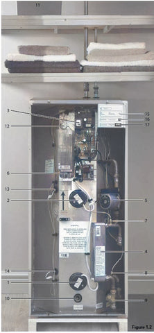
The standard configuration of the PulsaCoil A-Class is shown opposite. The Printed Circuit Control Board (A.C.B.), mounted inside the appliance, controls the operation of the complete system. This is pre-wired to a terminal strip where all electrical connections terminate. It is supplied with the following factory fitted equipment:-
1. 3kW Off-Peak immersion heater
2. 3kW On-Peak boost immersion heater
3. Printed Circuit Board
4. Plate heat exchanger
5. Domestic hot water primary (plate heat exchanger) pump
6. Isolating terminal connectors for dry fi re protection
7. DHW temperature sensor
8. Incoming cold water sensor
9. Strainer and fl ow regulator
10. Screwed connection for a drain tap
11. Top up cistern complete with cold feed/ open vent pipework assembly is supplied separately
12. Overheat thermostat
13. Middle store control sensor
14. Bottom store control sensor
15. Operation/warning light
16. Boost/reset button
17. On/Off switch
Note : Both immersion heaters are low watts density type with nicely 825 sheaths and are specially manufactured to suit Thermal Stores. It is recommended that any replacements should be obtained from Gledhill Water Storage.
Optional Extra Equipment
• Scale inhibitor for mains water services with hardness levels above 200 ppm (mg/l)
• Hot and cold water manifolds for use with plastic pipework.
• Ballvalve /overfly ow connector for top up cistern.
DESIGN

Appliance Dimensions
| Model | Height A |
Width B |
Depth C |
| PCA145 | 1042 | 530 | 595 |
| PCA185 | 1142 | 530 | 595 |
| PCA215 | 1300 | 530 | 595 |
| PCA235 | 1440 | 550 | 595 |
Note: The Appliance dimensions above do not allow for the100mm high installation base.
The following table of minimum cupboard dimensions only allow the minimum space required for the appliance (including the F & E cistern). Any extra space required for shelving etc in the case of airing cupboards etc must be added.
Minimum Cupboard Dimensions
| Model | Height D | Width E | Depth F |
| PCA145 | 1800 | 550 | 600 |
| PCA185 | 1900 | 550 | 600 |
| PCA215 | 2050 | 550 | 600 |
| PCA235 | 2200 | 570 | 600 |
Note: The above dimensions are based on the Appliance and the Top up cistern (fitted with aballvalve) being in the same cupboard. If the manual fill method is chosen the heights can be reduced by 125mm.
If pipework needs to rise vertically adjacent to the appliance the width/depth will need increasing to accommodate this.
DESIGN
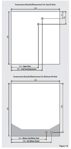
Note: All dimensions are shown in mm and are to the centre line of the pipework.
DESIGN
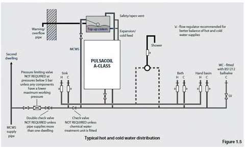
Hot and Cold Water System
General
DESIGN
Hot and Cold Water System
Pipe Sizing / Materials
Hot and Cold Water System
DESIGN
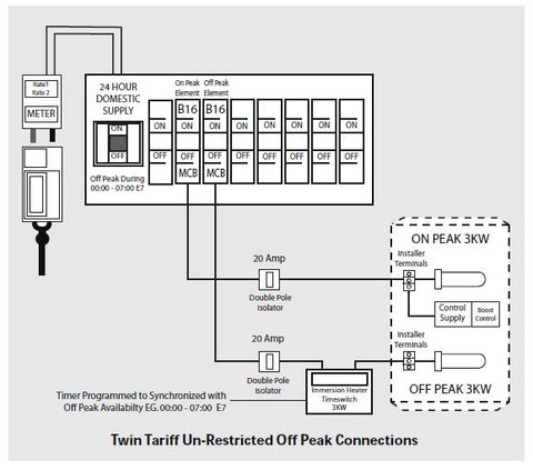
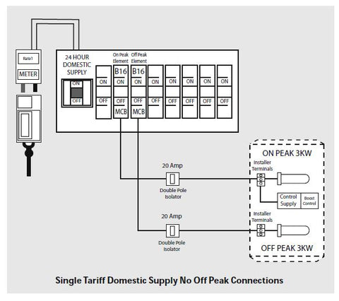
Electrical Installation
The size of the appliance and the need to use the on peak boost facility is reduced if a better off peak tariff can be agreed with the electrical supply company - see Model Selection Guide on page 5.
DESIGN

INSTALLATION
For Gledhill PulsaCoil A-Class Parts and Spares click on the following links: Gledhill PulsaCoil A-Class Parts And Spares
The appliance is designed to be installed in an airing/cylinder cupboard and the relevant minimum dimensions are provided in the Technical Data section of this manual.
Because of the ease of installation we recommend that the cupboard construction is completed and painted before installation of the appliance. The cupboard door can be fitted after installation.
If the unit needs to be stored prior to installation it should be stored upright in a dry environment and on a level base/floor.
Installation and maintenance access is needed to the front of the appliance and above the Top up cistern. See the Technical Data section of this manual for further details.
The minimum dimensions contained in the Technical Data section of this manual allow for the passage/connection of pipes to the appliance from any direction as long as the appliance is installed on the installation base provided. If the installation base is not used extra space may be needed to allow connection to the pipework and the whole of the base area should be continuously supported on a material which will not easily deteriorate if exposed to moisture.
The floor of the cupboard needs to be level and even and capable of supporting the weight of the appliance when full. Details of the weight when full is provided in the Technical Data section of this manual.
The appliance is designed to operate as quietly as practicable. However, some noise (from pumps etc) is inevitable when hot water is being used. This will be most noticeable if the cupboards are located adjacent to bedrooms, on bulkheads, or at the mid span of a suspended floor. Some noise may also be experienced from the immersion heaters as the store approaches its design temperature.
Cupboard temperatures will normally be slightly higher than in a conventional system and the design of the cupboard and door will need to take this into account. No ventilation is normally required to the cupboard.
The separate Top up cistern will need to be located on top of the appliance or at high level in the cupboard housing the PulsaCoil A-Class. The dimensions and clearances are provided in the Technical Data section of this manual. The location will need to provide a suitable route for the cold feed expansion pipe as well as the open safety vent pipe. The location will also need to provide a suitable route and discharge position for the warning/overfl ow pipe and the ballvalve supply from the mains cold water system (if provided) if these have been ordered as an optional extra.
Note: The standard appliance is supplied with a cistern without a ballvalve/ overfl ow for filling manually.
An electrical supply must be available which is correctly earthed, polarized and in accordance with the latest edition of the IEE requirements for electrical Installations BS 7671.
The electrical mains supply needs to be 230V/50Hz.
The sizes/types of electrical supplies must be as detailed in System Details section of this manual. A means for disconnection from the supply mains having a contact separation in all poles that provides full disconnection under over voltage category III conditions must be incorporated in the fixed wiring in accordance with the wiring rules. This shall be located within 1m of the appliance and only serve the appliance.
The hot and cold water ‘first fi x’ pipework should be terminated 50mm above the finished floor level in accordance with the dimensions provided in the Technical Data section of this manual.
INSTALLATION

Preparation/placing The Appliance In Position.
The ‘first fix’ pipework positions should be checked using the template provided with each appliance. If these have been followed installation is very simple and much quicker than any other system.
The appliance is supplied shrink wrapped on a timber installation base. Carrying handles are also provided in the back of the casing.
The feed and expansion cistern complete with ballvalve, cold feed/expansion and overflow/ warning pipe fittings are provided in a separate box.
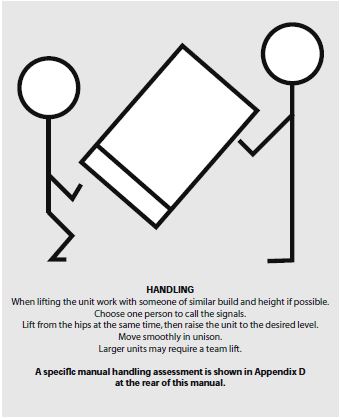
The appliance should be handled carefully to avoid damage and the recommended method is shown above.
Note: Although the above guidance is provided any manual handling/lifting operations will need to comply with the requirements of the Manual Handling Operations Regulations issued by the H.S.E.
The appliance can be moved using a sack truck on the rear face although care should be taken and the route should be even.
In apartment buildings containing a number of storeys we would recommend that the appliances are moved vertically in a mechanical lift.
If it is proposed to use a crane expert advice should be obtained regarding the need for slings, lifting beams etc.
Before installation the site requirements should be checked and confirmed as acceptable.
The plastic cover and protective wrapping should be removed from the appliance and the installation base (provided) placed in position.
The appliance can then be lifted into position in the cupboard on top of the base and the front panel removed by unscrewing the 2 screws and lifting the door up and out, ready for connection of the pipework and electrical supplies.
The feed and expansion cistern support shall be installed ensuring that the base is fully supported, the working head of the appliance is not exceeded and the recommended access is provided for maintenance - see the Technical Data section of this manual for details.
INSTALLATION
Pipework Connections
The position of the pipework connections is shown opposite. The exact location dimensions are listed in the Technical Data section of this manual.
All the connections are also labelled on the appliance. It is essential that the pipework is connected to the correct connection.
Connections A and B are plain ended copper pipe. Connection C and D compression fittings. Connection E is RC½ (½ in BSPT internal)
A - 22mm Safety open vent
B - 15mm Cold feed/expansion
C - 22mm Incoming mains cold water
D - 22mm Domestic hot water
E - ½” Drain tap connection
Note: The safety open vent and cold feed/ expansion must be connected to the top up cistern using the pipework assembly provided. Do not alter or connect any pressure-relief device to the vent pipe of this water heater.
All factory made joints should be checked after installation in case they have been loosened during transit.
The fittings for the top up cistern should be installed following the instructions provided and the cistern fitted on its supports/top of the appliance.
The cold feed/expansion and safety open vent should be installed between the appliance and the top up cistern.
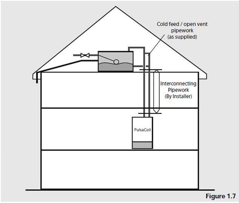
It is normally envisaged that the top up cistern will be located in the same cupboard as the PulsaCoil A-Class appliance itself to maintain a dry roof space.
The cold feed/open vent pipework assembly (as supplied) should be used to install the top up cistern directly on top of the appliance.
If it is necessary to locate the cistern in the roof space (or on a higher floor) the cold feed/open vent pipework assembly (as supplied) should be used to connect to the top up cistern and pipework site run by the installer to connect this to the appliance.
Obviously, any pipework in the roof space and the feed and expansion cistern will need to be adequately insulated to protect against frost damage.
Combined Feed And Open Pipe Arrangements Must Not Be Used.
No valves should be fitted in the safety open vent which must be a minimum of 22mm copper pipe or equivalent throughout its length.
The mains cold water supply to the ballvalve (if provided) shall be provided with a suitable servicing valve.
The overflow/warning pipe (if provided) shall have a continuous fall, be fitted to discharge clear of the building and be sited so that any overflow can be easily observed. It shall also be installed in a size and material suitable for use with heating feed and expansion cisterns in accordance with BS 5449 (e.g 22mm copper) and should not have any other connections to it.
Note: If a warning/overflow pipe is NOT provided the top up cistern should be filled from a temporary hose connection supplied from any cold water tap or from a permanent cold branch provided adjacent to the top up cistern. The temporary hose must be fitted with a double check valve and removed once the appliance is filled.
The store may fill more slowly than the feed tank. It is important to check the water level again in the cistern after commissioning.
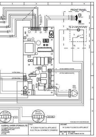
The PulsaCoil A-Class is pre-wired internally, strictly in accordance with the IEE Requirements for Electrical Installations BS 7671. The external wiring /connections should be carried out by a competent person to the same standard. The arrangement of the internal wiring is shown on the previous page.
Note: Do not attempt the electrical work unless you are competent to carry it out to the above standards.
Before commencing check that the power source is in accordance with the Site Requirements section of this manual and ensure that it is isolated as shown in the System Details section.
Run the external wiring from the adjacent isolator through the service slot provided in the base of the appliance.
Make the connections as shown below.
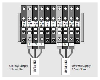
Clamp the cables in the grips provided and ensure all cables are routed to avoid hot surfaces.
Note: The appliance pipework should be bonded to earth to comply with the IEE Requirements for Electrical Installations BS 7671.
Before switching on the electrical supply check all the factory made terminal connections to ensure they have not become loose during transit.
INSTALLATION
Open the incoming stop valve and fill the domestic mains cold and hot water systems including the PulsaCoil A-Class appliance.
Check the water level in the top up cistern and if a ballvalve is fitted adjust if
necessary.
Check the whole of the domestic hot and cold distribution systems for leaks. Fully flush and if necessary chlorinate the hot and cold water system in accordance with the recommendations in the Water Regulations and BS 6700.
Please note that the whole of the domestic hot and cold water systems including the appliance must be adequately flushed after chlorination. Failure to do this can cause damage to the plate heat exchanger/immersion heaters etc. If there are any doubts regarding this or the quality of the water being used to fill the PulsaCoil appliance an inhibitor such as Fernox MBI or Sentinel X100 should be added to the appliance when filling in line with the manufacturers instruction for these products.
If a ballvalve is provided, turn down the servicing valve once the system is finally filled to the point where the warning/overflow pipe will cope with the discharge arising from a ballvalve failure.
If an overflow is not provided ensure the temporary filling hose is isolated and removed from its connection to the cold water supply.
It is essential that all systems function properly for optimum performance.
To achieve this the flow rate from each tap should be checked and a suitable number of taps run simultaneously to check the impact of this on the flow rate at individual taps.
We recommend that flow regulators are provided for each tap/terminal fitting to ensure that the available flow is shared evenly - See Appendix A for further details.
Commissioning the PulsaCoil Control System
Once the PulsaCoil A-Class is filled with water, check the on/off switch on the front is in the off position. The electrical supplies can then be switched on and the switches on the two isolating terminal connectors can be pushed home.
WARNING - Pushing home these switches will complete the electrical circuit to the immersion heaters. DO NOT PUSH HOME THESE SWITCHES AND SWITCH ON THE ELECTRICITY SUPPLY UNTIL YOU HAVE CHECKED THAT THERE IS WATER IN THE F & E CISTERN. Failure to do this can result in dry fi ring and premature failure of the immersion heaters, which will invalidate the warranty.
Put the on/off switch on the front control panel to the on position to activate the appliance control board. The switch will glow green when in the on position.
If an off peak supply is not available the onpeak boost immersion heater will need to be switched on by pressing the black button. The red light will change to permanently on.
It can be checked that the boost immersion heater is drawing current by use of a clamp meter on the live supply when boost is active or by interrogating the printed circuit control board in accordance with the instructions in the fault finding section of this manual.
The sensor control set points are shown on page 25 and can be checked on the 2 digit ACB display.
The boost immersion heater can be switched off by pressing again the black button.
If an off peak supply is available at the time the appliance is switched on the appliance will automatically switch on the off peak immersion heater. Its operation can be checked in the same way as described above for the on peak immersion heater. When the off peak supply is available the on peak immersion heater operation can still be checked as described above by switching off the off peak supply.
Note: If the on and off peak supplies have been connected wrongly (“crossed”) at the appliance it will not operate properly (it may charge if off peak is available but will not carry out any other operations)
If the appliances has been connected with the polarity incorrect it will not operate at all.
See the fault finding section of the manual for further details.
Run a tap and using a digital thermometer check that the temperature of the hot water is about 52°C. This temperature is factory set and is independent of the store temperature assuming the store is above 55°C and typical hot water flow rates of 6-25l/min are being drawn.
This product is covered by the ‘Benchmark’ scheme and a separate commissioning/ service log book is included with this product. This must be completed during commissioning and left with the product to meet the Warranty conditions offered by Gledhill.
SERVICING
For Gledhill PulsaCoil A-Class Parts and Spares click on the following links: Gledhill PulsaCoil A-Class Parts And Spares
Important Do’s and Don’ts
1. DO check the incoming mains water pressure. The preferred range of mains pressure is 2 -3 bar.
2. DO check the flow rate of the incoming cold water main is adequate to meet the maximum hot and cold water simultaneous demands.
3. DO check that all connections are in accordance with the labelling on the thermal store.
4. DO NOT push home the 2 switches on the isolating terminal connectors and switch on the electricity supply until you have checked that the appliance is full of water i.e. there is water in the top up cistern.
5. DO check the water level is correctly set in the top up cistern when cold and if fitted that there is no overflow when the appliance is up to temperature.
6. DO check that the sensors switch the immersion heaters off at the correct set point i.e. approx. 70°C.
7. DO insulate any exposed hot water pipework in the PulsaCoil cupboard.
8. If the ballvalve in the F & E cistern is permanently connected to the mains cold water supply DO plumb the overflow/warning pipe in a 20mm internal diameter pipe and ensure it discharges in a conspicuous external position. Use a material which is suitable for use with heating F & E cisterns in accordance with BS 5449 (such as copper).
9. DO ensure the green light ‘on/off’ switch glows.
10. Once the appliance is filled and commissioned DO leave the electricity switched on to the appliance to ensure the automatic pump run facility can operate to prevent the pump sticking.
11. DO ensure that the functioning and control of the system is explained to the occupant.
12. DON’T place any clothing or other combustible materials against or on top of this appliance.
These instructions should be placed along with the component manufacturers instructions in the pocket provided on the rear of the front panel. The front panel should then be refitted.
Annual Servicing
No annual servicing of the PulsaCoil A-Class is necessary.
However, if required, the operation of the controls and a hot water performance test can be carried out to prove the appliance is working satisfactorily and within its specification.
If it is decided to carry out the above tests the water level in the top cistern should also be checked and if necessary topped up.
Changing Components
Free of charge replacements for any faulty components are available from Gledhill during the in-warranty period on return of the faulty part (normally 12 months).
After this, spares can be obtained direct from supplieddirect.co.uk
However, all components are readily accessible and can be changed quickly and easily by the installer using common plumbing/electrical practice.
Note: All maintenance work on the PulsaCoil appliance must be carried out by a competent trades person.
Note: The pump is a Grundfos UPR 15-50 4 wire pattern and any replacement must be the same model.
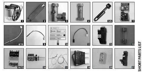
SERVICING
For Gledhill PulsaCoil A-Class Parts and Spares click on the following links: Gledhill PulsaCoil A-Class Parts And Spares
| Description | Supplier & Model | Part Number | Part Number | |
| 1 | PHE pump | Grundfos, UPR 15-50 | 5950543 | GT089 |
| 2 | Plate heat exchanger (PHE) | SWEP, 24 Plate heat exchanger | E8T/24 | GT017 |
| 3 | Pump isolating valve - outlet | Watt Industries, 90° valve | 7308123 | GT135 |
| 4 | Pump isolating valve - inlet | Watt Industries | GT133 | |
| 5 | Top immersion heater | Shell, 14” Immersion heater - no stat | Incalloy 825 | XB083 |
| 6 | Bottom immersion heater | Shell, 14” Immersion heater - no stat | Incalloy 825 | XB083 |
| 7 | Main PCB controller | Argus Vision 147/4GS controller | 47/4GS | GT490 |
| 8 | Middle sensor | Tasseron, Single sensor | TSK10B4 | GT198 |
| 9 | Top (OHT) sensor | Tasseron, Duplex sensor | TSK11B4 | GT199 |
| 10 | Front panel display | RH Technical, Membrane overlay | P210328 | XB411 |
| 11 | Front panel display harness | RH Technical, Membrane harness | XB057 | |
| 12 | Off-Peak circuit fuse holder | Phoenix, (Part of DIN rail assembly-non stock item) | ||
| 13 | Control & off-peak circuit fuses | RS Components, 5A FF | 415-626 | XB382 |
| 14 | Off-Peak/On-Peak contactor | Duracool | XB178 | |
| 15 | Bracket | Duracool | XB178 | |
| 16 | Complete DIN rail assembly | Phoenix, Bespoke terminal and component assembly |
XB180 | |
| 17 | Complete wiring harness | |||
| 18 | On-Off switch (part of panel) | Arcoelectric, Green illuminated rocker switch | C5503-ALNAK | CA006 |
| 19 | DHW inlet & outlet sensors | Tasseron, single sensor complete with nut & olive | Wet pocket sensor, comes as a kit. |
GT198 + GT295 |
| 20 | Relay | Relpol | RM87N-2311- 35-5230 |
XB424 |
| 21 | DIN rail socket |
Relpol
|
GZT92 | XB425 |
SERVICING
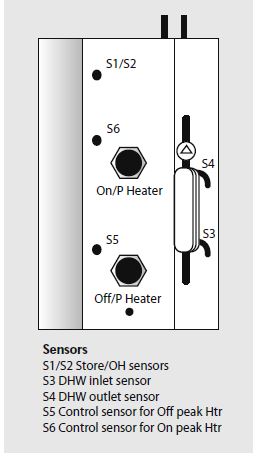
The PulsaCoil A-Class appliance control panel and printed circuit control board/display have been designed to be fully automatic whilst able to provide functional and diagnostic information to the householder/installer.
The panel/board work in conjunction with a number of sensors (thermistors) located as shown in the diagram below.
Automatic Control Operation
Heating of the store is controlled by sensors S1/S2 and S5 and S6. The control set points are shown in the table on page 25.
During normal charging cycle sensor S5 will control the bottom off peak I.H. in the same way S6 will control the top on peak I.H. when manually activated.
In the event of either of these sensors failing, control will be taken over by sensors S1/S2.
Normally, sensors S1/S2 are used to detect an overheat condition (over 95ºC) which will cause the red LED on the front control panel to fl ash (rapid).
This condition should not normally be reached as sensors S1/S2 will also switch off the supplies to the I.H’s if a temperature above 85ºC is detected. Normal operation will automatically resume when the temperature at the sensors drops below 78ºC.
The hot water temperature is controlled by sensors S3 and S4.
S3 checks for a drop in temperature every second and if the drop is more than 2ºC, it switches on the hot water pump to raise the domestic hot water temperature to 52ºC (± 2°C).
The control of the hot water temperature is carried out by sensor S4 adjusting the speed of the hot water pump.
The pump is stopped once S3 reaches a temperature of above 30°C.
The following checks should be carried out by the installer before calling the manufacturer.
Noise When Hot Water Tap Is Opened/closed
If the plate heat exchanger pump is noisy when the hot water tap is opened, then check the level of water in the F & E cistern and vent the pump if necessary.
Water hammer - loose pipework and/or tap washers and/or washing machine
valves.
Causes of ‘Unsatisfactory Hot Water Service’
See table opposite.
Check that the controlled level of water in the cistern is at the correct level. Adjust if required and check the ballvalve is shutting off the water supply.
| Fault Condition | Possible Causes |
| DHW temperature remains cold exiting the taps. |
- Thermal store is cold/DHW pump is permanently stuck - Temperature sensor or printed circuit control board is faulty. - The water level is low in the F&E Cistern - Overheat stat tripped - One or both immersion heaters have failed |
| DHW temperature fluctuates wildly when flow is steady |
- DHW pump keeps sticking intermittently - Hot & cold crossed at appliance. |
| DHW temperature exceeds and remains well above 60°C when the flow rate is low. |
- DHW printed circuit control board and/or temperature sensor is/are faulty. - Immersion heater thermostat temperature setting too high should be 70°C. |
| Store not heating | - The two switches on the isolating terminal connectors are not pushed home - i.e. unit is not commissioned. - No power supplies/fuses are blown. - Overheat stat has tripped. - One or both immersion heaters have failed. |
SERVICING
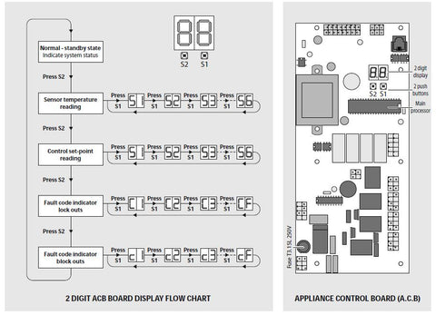
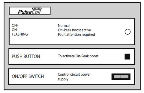
Appliance Control Board
The appliance control board (shown opposite) has a 2 digit display and 2 push buttons which are used to check the status of the appliance, check and set its identity and interrogate it for the current faults and the fault history.
The 2 digit display is controlled by 2 buttons S1 and S2. The fl ow chart of display modes is shown above. Generally, each press of button S2 cycles the display from top to bottom and each press of button S1 cycles the display functions from left to right.
The button S2 is also used to reset the appliance i.e. clear the lockout errors and reset the appliance. (Note: Appliance resetting can also be carried out using the push button on the front panel)
Note: The board is used on a range of products and not all terminals are used on every appliance.
Display in Normal (Standby) Mode
In the standard/normal mode the 2 digit display indicates the status of the appliance inputs and outputs by switching on the appropriate segments of the display - see page 24 for details.
Appliance Type Selection
The PulsaCoil is fitted with an identity (ID) resistor which is read by the controller for comparison with the appliance type (code) set on the controller. The two must match for the controller/appliance to function. Therefore if either the appliance code setting or the ID resistor is wrong, the appliance will shut down safely and flag the error code until the fault is rectified. The controller codes and the ID resistor values for the PulsaCoil are 03 and 3K3 respectively. The procedure for checking and setting the appliance code on the controller is described below.
• The appliance selection menu (A0 ... A9) on the controller is hidden. It is only possible to get to the appliance selection using the reset button (Left hand, S2) on the main board.
• When going from the show ‘ locking error’ to show ‘blocking error’ menu (see opposite), do not release the button but hold it for 10 seconds. The display will change from ‘c’ to ‘A’. At this stage the push button (S2) can be released.
• The appliance type can now be selected by using right hand push button, S1, e.g. for this appliance A03.
Press the reset button, S2, to accept the setting.
If the selected appliance code does not match with the ID resistor fi tted to the appliance, then, an error ‘33’ will be displayed.
SERVICING

| S1 | Top immersion heater sensor on (S6) | 70°C |
| S2 | Top immersion heater sensor off (S6) | 78°C |
| S3 | DHW in (S6) | 35°C |
| S4 | DHW out (S6) | 52°C |
| S5 | Bottom immersion heater sensor on (S6) | 75°C |
| S6 | Bottom immersion heater sensor off (S6) | 79°C |
| Code | Code | ||
| 10 | Overheat error | 45 | S1 overheat 1 shorted |
| 30 | Phase error | 48 | I.D. resistor shorted |
| 33 | Appliance selection | 49 | S4 sensor shorted |
| 37 | S1 overheat 1 open | 50 | S5 sensor shorted |
| 40 | I.D. resistor open | 51 | S6 sensor shorted |
| 41 | S4 sensor open | 52 | S2 overheat 2 shorted |
| 42 | S5 sensor open | 55 | Top IM failure |
| 42 | S6 sensor open | 56 | Bottom IM failure |
| 44 | S2 overheat 2 open |
Any other code displayed should be checked against the full chart.
This is designed for operation by the householder and the operation is in line with the instructions on the panel.
If a sensor error is detected one of the following three error codes flash alternately with the sensor number instead of the temperature
E1 Open circuit
E2 Short circuit
E3 Temperature greater than 99°C
A code of FF indicates the fault location is empty.
The set point reading mode is normally only used by the Gledhill engineer to check the sensor set points are still correct. The set point alternately flashes with S1-S6.
See table opposite for set points.
Note: The S1-S6 reference display does not correspond with the S1-S6 sensor references used earlier. These are shown in brackets on the table opposite.
The two fault code indication modes are again mainly for use by the Gledhill engineer and can only be used with a reference table.
The Blocking errors will clear automatically when the fault is cleared/component changed. The Locking errors can only be cleared by resetting the controller.
In each case there are 16 fault locations stored in date order with C0 being the latest and CF the first.
The most common fault codes are shown opposite. Not all appliances use all the error codes available.
APPENDIX
Water Savings
Water Related Costs Can Be Reduced By Good Plumbing Practice
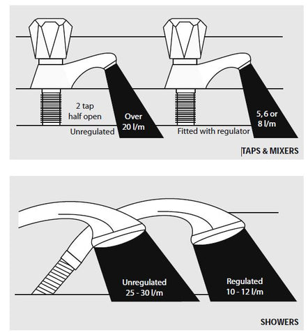
Vast quantities of water are needlessly run off to waste due to Taps, Mixers and Showers discharging flow rates far in excess of the rates required for them to perform their duties.
The contrasting flow rates shown on this leaflet clearly illustrate the savings that can be made whilst still providing a good performance.
British made Aquaflow Regulators provide constant flow rates by automatically compensating for supply pressure changes between 1 bar & 10 bars.
To facilitate installation into the wide range of plumbing equipment which is encountered in the U.K, Four Fixing Options are available:-
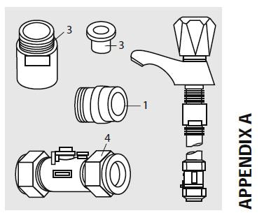
Options For Showers
1. MXF “DW” Range - For fitting behind Fixed Shower Heads or onto Flexible Hoses for Handshowers (preferably onto the inlet end when lightweight hoses are used).
2. Compression Fitting Range. “In Line” regulators as in Option 4 for Taps & Mixers.
Information by courtesy of
AQUAFLOW REGULATORS LTD
Haywood House, 40 New Road, Stourbridge, West Midlands DY8 1PA
TELEPHONE (01384) 442611 FAX: (01384) 442612
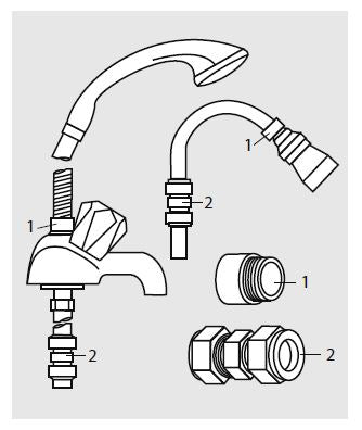
1. MK Range - Combined Regulators & Aerator for screwing onto Taps & Mixers with internal or external threads on their noses. Anti Vandal models also available.
2. MR05-T Range - Internal Regulators. Pushfit into Tap or Mixer seats. Produced in three sizes - 12.5mm (BS1010), 12mm & 10mm, Flangeless models also available for Taps with Low Lift washers.
3. MXF Standard Range - Screw on tail models for Taps & Mixers. Fix onto the tails before fitting the tap connectors. Available in 3/8", 1/2", 3/4" and 1" BSP.
4. Compression Fitting Range - “In Line” regulators housed in 15mm & 22mm CXC Couplers & Isolating Valves. “ ”UK WFBS listed by the Water Research Centre. Isolation valves available for slotted screwdriver operation or with coloured plastic handles. Now available also in plastic bodied push-fit couplers & valves.
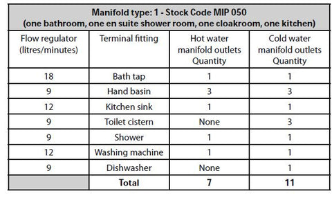
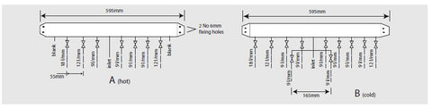
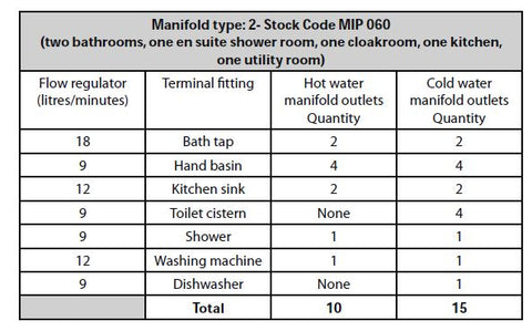
The manifolds are designed to be used with plastic pipework and are supplied complete with isolation valves and flow regulators on each branch. They would normally be installed in the same cupboard as the thermal storage appliance (as shown below) but can be installed in another cupboard close to the appliance if required.
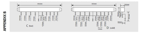
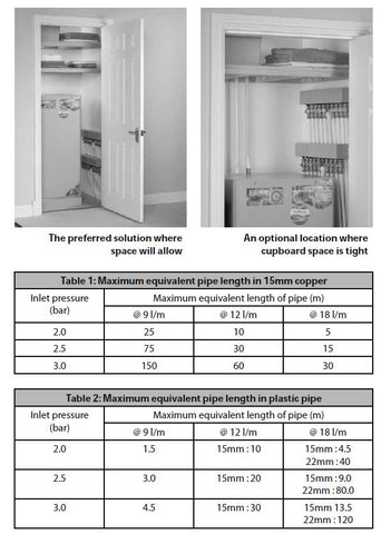
The maximum equivalent pipe lengths from the manifold to the terminal fittings can be estimated from the above information and the resistance characteristics of the pipes. The examples presented below are for 15mm copper pipe in table 1 and for plastic pipework in table 2.
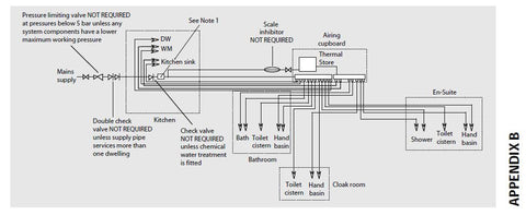
The size of the distribution pipes supplying the manifold should be calculated using the method set out in BS 6700. A typical diagrammatic arrangement of a system using Manifold Type 1 is shown below.
This is only meant to show the principles involved and the actual connection of fittings to the manifold will need to suit the arrangements shown on page 42.
Note: If it is proposed to fit chemical water treatment such as a water softener this should be fitted in this location and the cold water branch in the sink should be branched off the cold water main prior to the treatment device instead of the cold water manifold.
Any other isolating/control valves and backflow protection devices should be provided as necessary to comply with the Water Regulations.
MANUAL HANDLING OF APPLIANCE PRODUCTS
Manual handling means any transporting or supporting of a load (including lifting, putting down, pushing, pulling, carrying or moving) by hand or bodily force.
Scope
This assessment will cover the largest Appliance, namely ElectraMate, GulfStream, BoilerMate, SysteMate, PulsaCoil, Accolade and Stainless Lite manufactured by Gledhill.
The maximum weight of the largest product in each range is 98kg and the size is 595 x 595 x 2020 mm high.
Main Hazards
Vision may not be clear due to the size of the products.
Adopting an incorrect method of lifting may cause injury, attempting to lift these
products will require help from others. (Team lifts)
Control Measures
Manual lifting procedure
The lift, key factors in safe lifting are:
a. Balance
b. Position of back
c. Positioning of the arms and body
d. The hold
e. Taking the lead for team lifts
a. Balance - Since balance depends essentially upon the position of the feet, they should be apart about hip breadth with one foot advanced giving full balance sideways and forward without tension. In taking up this position, lifting is done by bending at the knees instead of the hips and the muscles that are brought into use are those of the thigh and not the back.
b. Position of back - Straight - not necessary vertical. The spine must be kept rigid, this coupled with a bent knee position, allows the centreline of gravity of the body to be over the weight so reducing strain.
c. Positioning of arms and body - The further arms are away from the side, the greater the strain on the shoulders, chest and back. Keep elbows close to the body arms should be straight.
d. The hold - Before lifting ensure you have a good hold. Two handles are provided on Appliance products at the top rear side, these allow one or two persons to have a purposely-designed hold at the top of the appliance to ensure easy lifting at the top of the product. Each appliance is supplied with a pallet, which has been attached to the unit via the packaging. The pallet will also allow for one or two persons to get a good hold.
e. Taking the lead for team lifts- As more than one person is required for these products ensure that one person is taking the lead. This may be you so ensure that each person that is helping is made aware of the weight and of the items listed within this assessment. Make sure you and any others helping know the route you intend to take that it is clear of any obstructions. Never jerk the load as this will add a little extra force and can cause severe strain to the arms, back and shoulders. If there are steps involved decide on where you will stop and take a rest period. Move smoothly and in unison taking care to look and listen to others helping with the lift. Where possible use a sack truck to move the product over long flat distances, only lift the products when necessary. If in doubt stop and get more help. The unit handles and packaging with the pallet have been designed to ensure that two-four people can assist when lifting up stairs or over longer distance.
Individual capability
Individual capability plays an important part in handling these products. Persons above average build and strength will find it easier and should be in good health. Persons below average build and strength may require more rest periods during the handling process. Pregnant women should not carry out this operation. Persons who are not in good health should seek medical advice prior to commencing any lifting or manual handling operation.
Residual risk
Following the guidelines given above will reduce any risk to injury. All persons carrying out this operation must be fully trained and copies of the specific risk assessment made available for inspection and use in their training process.
Further guidance on Manual Handling can be obtained from the Health and Safety Executive. Manual Handling Operations Regulations 1992.