
BoilerMate BP
For Gledhill BoilerMate BP Parts and Spares click on the following links: Gledhill BoilerMate BP Parts And Spares
Mains pressure hot water thermal store for use with gas or oil boilers
Design, Installation & Servicing Instructions

ISSUE 3: JANUARY 2014
| Section | Details |
| DESIGN | Introduction |
| Technical Data | |
| System Details | |
| INSTALLATION | Site Requirements |
| Installation | |
| Commissioning | |
| SERVICING | Annual Service |
| Changing Components | |
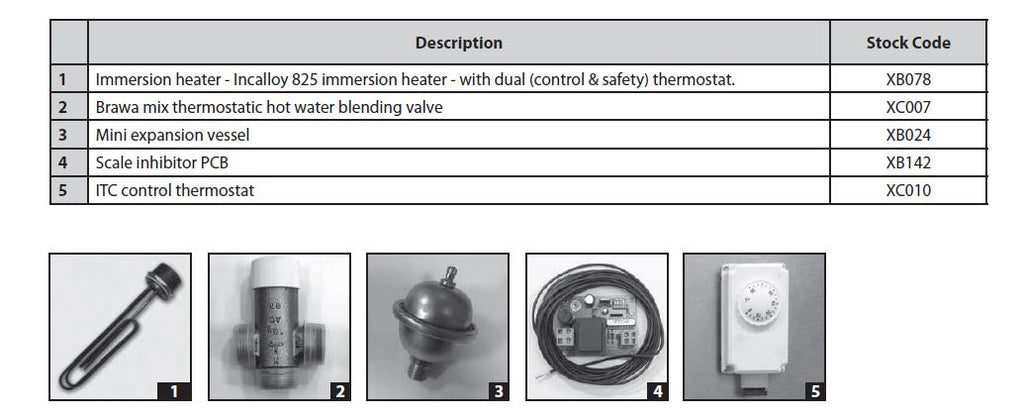
| Short Parts List | |
| Fault Finding | |
| APPENDIX | Appendix A |
| Appendix B | |
| Appendix C | |
| Notes | |
| Terms & Conditions | |
| BENCHMARK | Commissioning Checklist |
| Service Record |

Benchmark places responsibilities on both manufacturers and installers. The purpose is to ensure that customers are provided with the correct equipment for their needs, that it is installed, commissioned and serviced in accordance with the manufacturers instructions by competent persons and that it meets the requirements of the appropriate Building Regulations. The Benchmark Checklist can be used to demonstrate compliance with Building Regulations and should be provided to the customer for future reference.
Installers are required to carry out installation, commissioning and servicing work in accordance with the Benchmark Code of Practice which is available from the Heating and Hot Water Industry Council who manage and promote the Scheme. Visit www. centralheating.co.uk for more information.
For further information on the HWA Charter Membership, please refer to the HWA website hotwater.org.uk.
Gas Safe operates a Self Certification Scheme for gas heating appliances.
The Gledhill BoilerMate BP range is a WBS listed product and complies with the HWA Specification for integrated thermal storage products. The principle was developed in conjunction with British Gas. This product is manufactured under an ISO 9001:2008 Quality System audited by BSI.
Gledhill’s first priority is to give a high quality service to our customers.
Quality is built into every Gledhill product and we hope you get satisfactory service from Gledhill.
If not please let us know.
DESIGN
These instructions should be read in conjunction with the Installation and Servicing Instructions issued by the manufacturers of the heat source e.g. the boiler used.
Any water distribution and central heating installation must comply with the relevant recommendations of the current version of the Regulations and British Standards listed below:-
Gas Safety Regulations
Building Regulations
I.E.E. Requirements for Electrical Installations
Water Regulations
British Standards
BS6798, BS5449, BS5546, BS5440:1, BS5440:2, CP331:3, BS6700, BS5258, BS7593 and BS7671.
A suitably competent person as stated in the Gas Safety Regulations must install the BoilerMate and carry out any subsequent maintenance/repairs. In fact, the front panel is secured by 2 screws and should only be removed by a competent trades person. The manufacturer’s notes must not be taken as overriding statutory obligations.
The BoilerMate BP is suitable for use with either a sealed primary or an open vented central heating system.
The BoilerMate BP is not covered by section G3 of the current Building Regulations and is therefore not notifiable to Building Control.
The BoilerMate BP is not intended for use by persons (including children) with reduced physical, sensory or mental capabilities, or lack of experience or knowledge, unless they have been given supervision or instruction concerning use of the appliance by a person responsible for their safety.
Children should be supervised to ensure that they do not play with the appliance.
The information in this manual is provided to assist generally in the selection of equipment. The responsibility for the selection and specification of the equipment must however remain that of the customer and any Designers or Consultants concerned with the design and installation.
Please Note: We do not therefore accept any responsibility for matters of design, selection or specification or for the effectiveness of an installation containing one of our products unless we have been specifically requested to do so.
All goods are sold subject to our Conditions of Sale and Warranty Terms, which are set out at the rear of this manual.
In the interest of continuously improving the BoilerMate BP range, Gledhill Building Products Ltd reserve the right to modify the product without notice, and in these circumstances this document, which is accurate at the time of printing, should be disregarded. It will however be updated as soon as possible after the change has occurred.
Description
The BoilerMate BP is an indirectly heated hot water only thermal store. It is designed for use with a remote gas or oil boiler and is suitable for both open vented and sealed heating systems as long as they comply with the recommendations of contained in the rest of this manual. When it is used in a sealed heating system, the boiler should also be suitable for the sealed heating systems.
An important feature of this concept is that the hot water can be supplied directly from the mains at high flow rates without the need for temperature and pressure relief valves or expansion vessels. This is achieved by passing the mains water through the heat exchangers inside the thermal store. The outlet temperature of the domestic hot water is regulated by a thermostatic blending valve which is factory set at 55±3°C .
Because the BoilerMate BP does not require a safety discharge from a temperature and pressure (T&P) valve, the installations in buildings will be easier and will not suffer the problems associated with using the PVCu soil stacks to take discharge from the unvented cylinders.
The BoilerMate BP is supplied as an F&E cistern and ball valve to be fitted by the installer.
DESIGN
 Standard Equipment
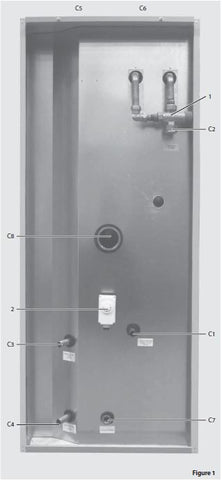
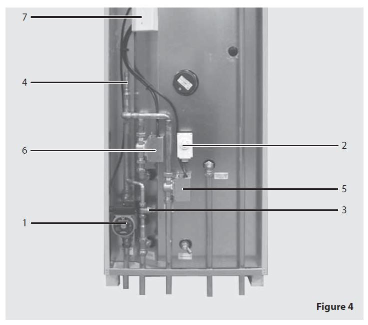
The standard configuration of the BoilerMateBP is shown opposite and it is supplied with the following factory fitted equipment: -
1 Thermostatic dhw blending valve – set at 55°C
2 Store thermostat – set at 75°C
3 Feed and expansion cistern complete with ball valve and float (not shown) – loose, to be piped by the installer
Factory Fitted Optional Equipment
A1 Electronic scale prevention device
Supply Only Optional Equipment
Immersion heater
Pipe Connections
The position of the pipe connections is shown opposite and the connection sizes are listed in table 1.
C1 Mains cold water inlet
C2 Hot water outlet
C3 Primary heat exchanger fl ow
C4 Primary heat exchanger return
C5 Open vent
C6 Cold feed
C7 Drain
C8 Immersion heater boss
All the connections are also labelled on the appliance. It is essential that the pipework is connected to the correct connection.
Note: The safety open vent and cold feed/ expansion must be connected to the F & E cistern using the pipework assembly provided. Do not alter or connect any pressure-relief device to the vent pipe of this water heater.
All factory made joints should be checked after installation in case they have been loosened during transit.
The fittings for the feed and expansion cistern should be installed in a position to suit the particular location and the cistern fitted on its supports/base.
The cold feed/expansion and safety open vent should be installed between the appliance and the feed and expansion cistern.
TECHNICAL DATA
DESIGN
Notes:-
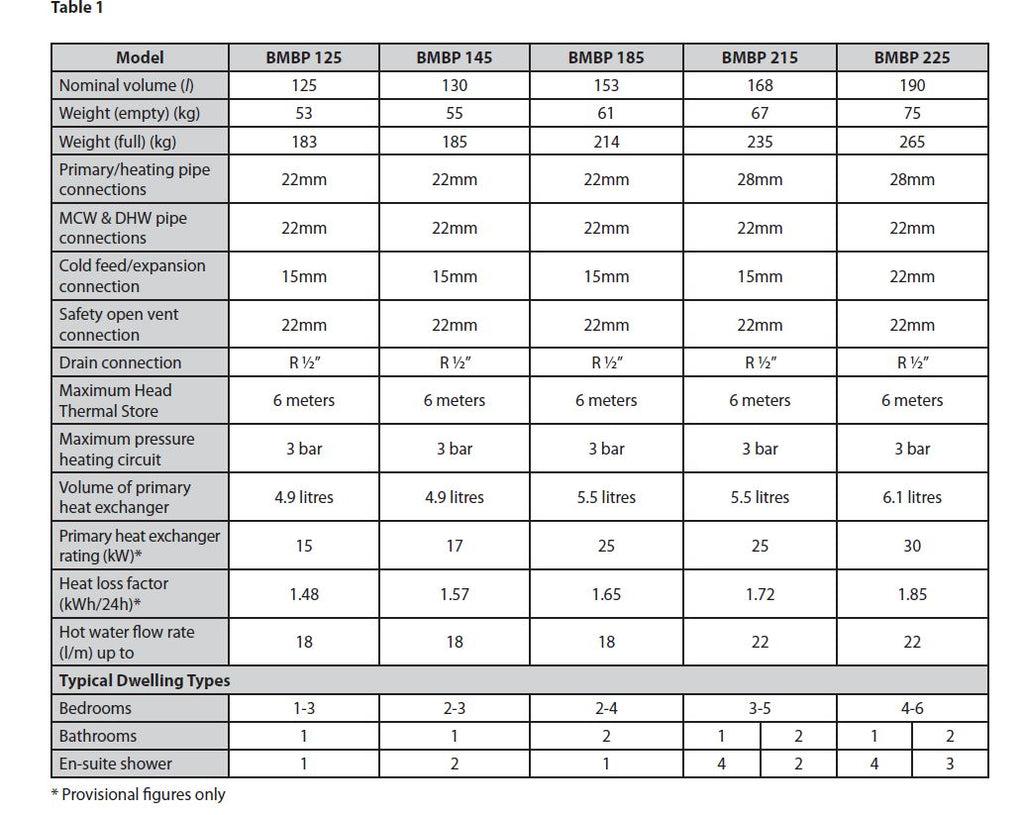
1. The flow rates are based on a 35°C temperature rise and assume normal dynamic pressure of 2.0 bar at the appliance.
2. Unit is supplied on a 100mm high installation base.
3. The domestic hot water outlet temperature is automatically regulated to approximately 55°C.
DESIGN
Appliance Dimensions
| Model | Height (A) | Width (B) | Depth (C) |
| BMBP 125 | 1262 | 580 | 595 |
| BMBP 145 | 1262 | 580 | 595 |
| BMBP 185 | 1423 | 580 | 595 |
| BMBP 215 | 1584 | 580 | 595 |
| BMBP 225 | 1784 | 580 | 595 |
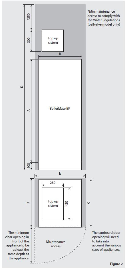
Note: The Appliance dimensions above do not allow for the100mm high installation base.
The following table of minimum cupboard dimensions only allow the minimum space required for the appliance (including the top up cistern). Any extra space required for shelving etc in the case of airing cupboards etc must be added.
| Model | Height (D) | Width (E) | Depth (F) |
| BMBP 125 | 2012 | 680 | 600 |
| BMBP 145 | 2012 | 680 | 600 |
| BMBP 185 | 2173 | 680 | 600 |
| BMBP 215 | 2334 | 680 | 600 |
| BMBP 225 | 2534 | 680 | 600 |
Note: The above dimensions are based on the Appliance and the Top up cistern (fitted with a ball valve) being in the same cupboard.
If the manual fill option is chosen, the heights shown above can be reduced by 125mm.
If pipework needs to rise vertically adjacent to the appliance the width/depth will need increasing to accommodate this.
DESIGN
Example installation of a ‘Y’ plan system
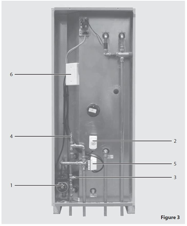
1 Pump
2 Store thermostat
3 Bypass valve
4 Manual air vent
5 3-port mid position valve
6 Wiring center
Note: All components to be supplied by the installer.
Example installation of an ‘S’ plan system
1 Pump
2 Store thermostat
3 Bypass valve
4 Manual air vent
5 Central heating zone valve
6 Hot water zone valve
7 Wiring centre
Note: All components to be supplied by the installer.
DESIGN
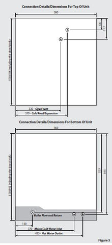
PLAN OF APPLIANCE CONNECTIONS
The BoilerMate BP units are supplied on an installation base to allow the pipe runs to connect to the appliance from any direction. It is easier if all pipes protrude vertically in the cut out area shown. Compression or push fi t connections can be used. All pipe positions are approximate and subject to a tolerance of +/- 10mm in any direction. Space will also be required for a 15mm cold water supply and a 22mm warning / overflow pipe.
Note: All dimensions are shown in mm and are to the centre line of pipework.
DESIGN

DESIGN
Hot and Cold Water System
General
A schematic layout of the hot and cold water services in a typical small dwelling is shown below. BoilerMate BP will operate at mains pressures as low as 1 bar and as high as 5 bar although the recommended range is 2-3 bar. These pressures are the minimum dynamic pressures at the cold connection to the BoilerMate BP at the time of the maximum calculated simultaneous demand. Particular consideration should also be given to available pressures in the case of 3 storey properties. It is also important to check that all other equipment and components in the hot and cold water system are capable of accepting the mains pressure available to the property. If the mains pressure can rise above 5 bar or the maximum working pressure of any item of equipment or component to be fitted in the system a pressure limiting (reducing) valve set to 3 bar will be required.
No check valve or similar device should be fitted on the cold water supply branch to the BoilerMate BP.
The Building Regulations L1A, L1B and the requirements set out in the Domestic Heating Compliance Guide specify that “where the mains water hardness exceeds 200ppm provision should be made to treat the feed water to water heaters and the hot water circuit of combination boilers to reduce the rate of accumulation of lime scale”.
To comply with this requirement the hardness of the mains water should be checked by the installer and if necessary the optional factory fitted in-line scale inhibitor should be specified at the time of order for hardness levels between 200 and 300 ppm (mg/l).
Where the water is very hard ie 300ppm (mg/l) and above the optional polyphosphate type, inhibitor should be specified at the time of order. However, this will need to be fitted by the installer at a suitable point in the cold water supply to the appliance.
If scale should ever become a problem the BoilerMate BP heat exchanger can be descaled in situe. Contact the Technical Helpline for more details.
The hot water flow rate from the BoilerMate BP is directly related to the adequacy of the cold water supply to the dwelling. This must be capable of providing for those services, which could be required to be supplied simultaneously, and this maximum demand should be calculated using procedures defined in BS 6700.
If a water meter is fitted in the service pipe, it should have a nominal rating to match the maximum hot and cold water peak demands calculated in accordance with BS 6700. This could be up to 80ltr/min in some properties.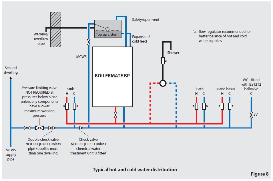
SYSTEM DETAILS
DESIGN
Hot and Cold Water System
Pipe Sizing / Materials
To achieve even distribution of the available supply of hot and cold water, it is important in any mains pressure system, that the piping in a dwelling should be sized in accordance with BS 6700. This is particularly important in a large property with more than one bathroom.
However, the following rule of thumb guide lines should be adequate for most smaller property types as long as water pressures are within the recommended range of 2-3 bar.
1. A 15mm copper or equivalent external service may be sufficient for a small 1bathroom dwelling (depending upon the flow rate available), but the minimum recommended size for new dwellings is 22mm (25mm MDPE). For the BMBP 225 model we recommend a 28mm (32mm MDPE) supply pipe.
2. The internal cold feed from the main incoming stop tap to the BoilerMate should be run in 22mm pipe. The cold main and hot draw-off should also be run in 22mm as far as the branch to the bath tap.
3. The final branches to the hand basins and sinks should be in 10mm and to the baths and showers in 15mm. (1 metre minimum)
4. If an external hose tap is provided this should be branched in 15mm pipework from the cold pipework as near to the incoming mains as possible.
5. We would recommend that best results for a balanced system are achieved by fitting appropriate flow regulators to each hot and cold outlet. This is particularly relevant where the water pressures are above the recommended water pressure range of 2-3 bar, or the dwelling is 3 storey. Details of suitable flow regulators are provided in Appendix.
All the recommendations with regard to pipework systems in this manual are generally based on the use of BS/EN Standard copper pipework and fittings.
However, we are happy that plastic pipework systems can be used in place of copper internally as long as the chosen system is recommended for use on domestic hot and cold water systems by the manufacturer and is installed fully in accordance with their recommendations.
It is also essential that if an alternative pipework material/system is chosen the manufacturer confirms that the design criteria of the new system is at least equivalent to the use of BS/EN Standard copper pipework and fittings.
Taps/Shower Fittings
Aerated taps are recommended to prevent splashing.
Any type of shower mixing valve can be used as long as both the hot and cold supplies are mains fed. However, all mains pressure systems are subject to dynamic changes particularly when other hot and cold taps/showers are opened and closed, which will cause changes in the water temperature at mixed water outlets such as showers. For this reason and because these are now no more expensive than a manual shower we strongly recommend the use of thermostatic showers with this appliance. These must be used in 3 storey properties where the impact on pressure/temperature of opening another tap in the system is greater than normal.
The shower head provided must also be suitable for mains pressure supplies.
However, if it is proposed to use a ‘whole body’ or similar shower with a number of high flow/pressure outlets please discuss with the Gledhill technical department.
The hot water supply to a shower-mixing valve should be fed wherever practical directly from the BoilerMate BP or be the first draw-off point on the hot circuit. The cold supply to a shower-mixing valve should wherever practical be fed directly from the rising mains via an independent branch. The shower must incorporate or be fitted with the necessary check valves to provide backsyphonage protection in accordance with the Water Regulations.
The supply of hot and cold mains water directly to a bidet is permitted provided that it is of the over-rim flushing type and that a type ‘A’ air gap is incorporated.
Hot and Cold Water System.\
If the length of the hot water draw off pipework is excessive the delivery time may be unacceptable before hot water is available at the tap, you may wish to consider using either trace heating to the hot water pipework such as the Raychem HWAT system or secondary circulation. Please consult Gledhill Technical Department for further details.
It is important that the cold water pipework is adequately separated/protected from any heating/hot water pipework to ensure that the water remains cold and of drinking water quality.
DESIGN
Heating System
General – Sealed And Open Vented Heating Systems
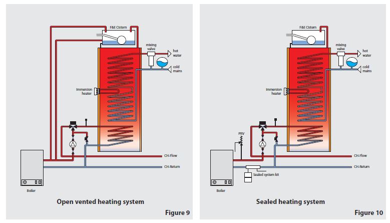
The BoilerMate BP is suitable for both an open vented and a sealed heating systems shown schematically in figures 9 and 10 respectively. The system components can be installed inside the appliance case as shown in figures 3 and 4.
Although, the heating system can be either open vented or sealed, the thermal store must always be open vented as shown in figures 9 & 10 and also: -
• The combined cold feed and open vent pipe arrangement must not be used.
• No valve should be fitted in the safety open vent and which must be a minimum of 22mm copper pipe or equivalent.
The BoilerMate BP is designed to be installed with condensing or non condensing oil or gas boiler which is capable of delivering hot water at a minimum temperature of 80°C.
The boiler must be set to operate at nominal 82°C flow which usually corresponds to maximum boiler control thermostat setting.
It is recommended that an automatic bypass is fitted to compensate for pressure and hence the flow rate changes in the heating circuit e.g. when the thermostatic radiator valves close. The bypass valve must be set by the installer to suit the system i.e. to provide minimum flow required for the boiler when all TRVs are closed.
DESIGN
Heating System
Pipe Sizing And Materials – Sealed And Open Vented Heating Systems
All the recommendations with regard to heating systems in this manual are generally based n BS/EN Standard copper pipework and fittings. However we are happy that plastic pipework system can be used in place of copper as long as long as the: -
• The chosen system is recommended for use in domestic heating systems by the manufacturers and it is installed fully in accordance with their recommendations.
• The design criterion of the plastic system is at least equivalent to the use of BS/En Standard copper pipework and fittings.
• We always recommend the barrier pipe for these systems.
• The F & E cistern supplied with the thermal store can be fitted remotely up to 6m above the base of the BoilerMateBP i.e. the maximum static pressure in the store must not exceed 0.6bar.
The primary pipework connecting the boiler, the thermal store and central heating system should be sized to achieve either 11°C rise across the boiler or the maximum temperature rise specified by the boiler manufacturer; which ever is smaller. But in any case should not be less than 22mm copper tube or equivalent.
The pressure loss through the primary heat exchanger is shown in figure 6 and this can be used for sizing the pump and the primary pipe work.
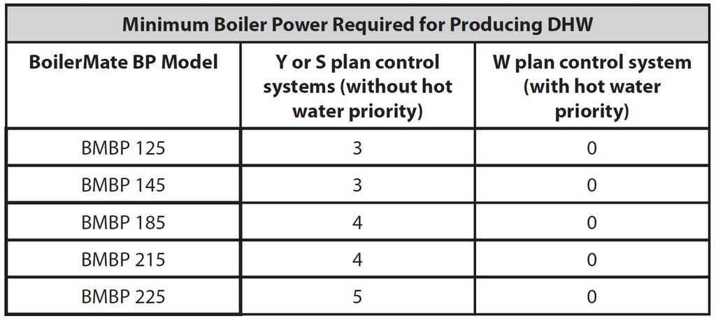
Boiler Size
The minimum total boiler power required is the sum of the power required for space heating which should be calculated in accordance with BS 5449 and the power required for producing hot water which can be read from table below.
DESIGN
Heating System
Open Vented Heating Systems
The layout of a typical open vented ‘Y Plan’ heating system is shown in figure 8. The BoilerMate BP is equally suitable for ‘S’ and ‘W’ plan heating system layouts.
The flow pipe from the boiler should rise continuously up to the vent pipe to facilitate venting. The heating circuit is taken directly from the boiler and is piped in the conventional manner.
The F & E cistern supplied with the thermal store can be fitted remotely up to 6m above the base of the BoilerMate BP. If this cistern is used for the central heating as shown in figure 8, then the water level in the F&E cistern should be at least 250mm above the highest point on the system including the radiators and must be high enough to provide the minimum head required by the boiler being used.
Sealed Heating Systems
The layout of a typical sealed ‘Y Plan’ heating system is shown in figure 9. The BoilerMate BP is equally suitable for ‘S’ and ‘W’ plan heating system layouts. A boiler used in a sealed heating system must be suitable for this application i.e. must be fitted with an overheat cut-out thermostat.
It is recommended that the F&E cistern (for the store) is fitted at a high level in the same cupboard as the BoilerMate BP. However it can be fitted remotely up to 6m above the base of the BoilerMate BP.
The F&E cistern overflow/warning pipe should be installed in a material suitable for a heating system feed and expansion cistern in accordance with BS5449.
There shall be no permanent connection to the mains water supply for filling the system even through a non-return valve without the approval of the Local Water Authority. An approved filling loop is required with for filling the system, which should be disconnected after commissioning the system. This should be located adjacent to the boiler along with a suitable expansion vessel, pressure gauge, pressure relief valve.
The table below can be used for sizing the heating system expansion vessel. The water content of the primary heat exchanger is listed in table 1 and a figure of 4.5 l/kW of installed radiator capacity can be used for a preliminary assessment of the water content of the heating system.
The expansion vessel requirements shown in table below are based on a maximum
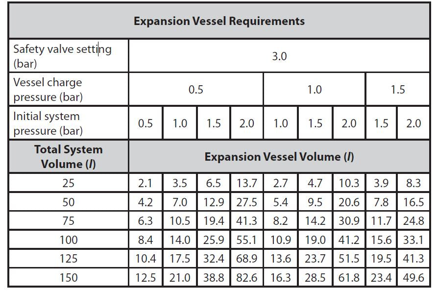
INSTALLATION
The appliance is designed to be installed in an airing/cylinder cupboard and the relevant minimum dimensions are provided in the Technical Data section.
Because of the ease of installation we recommend that the cupboard construction is completed and painted before installation of the appliance. The cupboard door can be fitted after installation. No ventilation is normally required to the cupboard.
If the unit needs to be stored prior to installation it should be stored upright in a dry environment and on a level base/floor.
Installation and maintenance access is needed to the front of the appliance and above the F & E cistern. See Technical Data section for further details.
The minimum dimensions contained in the Technical Data section allow for the passage/connection of pipes under the appliance from any direction as long as the appliance is installed on the installation base provided. If the installation base is not used extra space may be needed to allow connection to the pipework and the whole of the base area should be continuously supported on a material which will not easily deteriorate if exposed to moisture.
The floor of the cupboard needs to be level and even and capable of supporting the weight of the appliance when full. Details of the weight when full is provided in the Technical Data section.
The appliance is designed to operate as quietly as practicable. However, some noise (from pumps etc) is inevitable in any heating system. This will be most noticeable in cupboards formed on bulkheads, or at the mid span of a suspended floor. In these cases the situation can be improved by placing the appliance on a suitable sound deadening material (i.e. carpet underlay or similar).
A suitable location will be needed for the separate feed and expansion cistern. This will often be at high level in the cupboard housing the BoilerMate BP. The dimensions and clearances are provided in the Technical Data section. The location will need to provide a suitable route for the cold feed and expansion pipe as well as the open safety vent pipe. The location will also need to provide a suitable route and discharge position for the warning/overflow pipe and the ballvalve supply from the mains cold water system if the automatic fill version appliance is being fitted.
Note: The standard appliance is supplied with a cistern but without a ballvalve and overflow connector.
INSTALLATION
Electrical Wiring
1 An electrical supply must be available which is correctly earthed, polarized and in accordance with the latest edition of the IEE requirements for electrical Installations BS 7671.
2 The electrical mains supply needs to be 230V/50Hz.
3 A means for disconnection from the supply mains having a contact separation in all poles that provides full disconnection under over voltage category III conditions must be incorporated in the fixed wiring in accordance with the wiring rules. This shall be located within 1m of the appliance and only serve the appliance.
4 An optional 3kW 230Vac immersion heater complete with a thermostat and overheat cutout with manual reset can be fitted for heating domestic hot water in case the boiler fails. The immersion heater control thermostat must be set at 75°C. The wiring of the immersion heater must be in accordance with the relevant IEE wiring regulations as the circuit must be protected by a suitable fuse and a local double pole isolator.
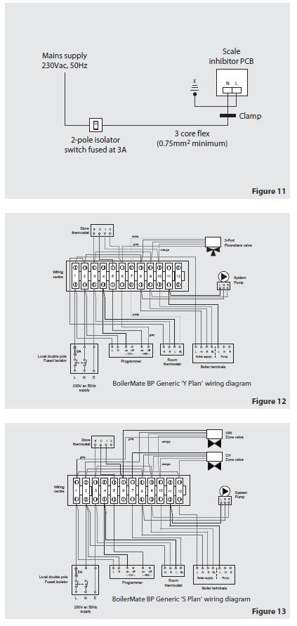
5 If an optional scale inhibitor device is fitted then a 3 core flex from the local 2-pole isolator fused at 3A should be used to connect 230Vac 50 hz supply to the controller terminals (see figure 11).
6 The 230Vac 50hz supply to the system wiring centre must be in accordance with the relevant IEE Wiring Regulations on the circuit must be protected by a suitable 5A fuse and a double pole local isolating switch (see figures 12 and 13)
INSTALLATION
Preparation/placing the appliance in position.
Details of the recommended positions for termination of the first fix pipework are provided in the Technical Data section. The pipework can be located or its position checked using the template provided with each appliance. If these have been followed installation is very simple and much quicker than any other system.
 The appliance is supplied shrink wrapped on a timber installation base with the F&E cistern on top of the unit. Carrying handles are also provided in the back of the casing.
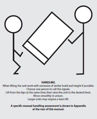
The appliance should be handled carefully to avoid damage and the recommended method is shown opposite. Before installation the site requirements should be checked and confirmed as acceptable. The plastic cover and protective wrapping should be removed from the appliance and the installation base (provided) and placed in position.
The appliance can then be lifted into position in the cupboard on top of the base and the front panel removed by unscrewing the 2 screws and lifting the door up and out, ready for connection of the pipework and electrical supplies. The feed and expansion cistern support shall be installed ensuring that the base is fully supported and the working head of the appliance is not exceeded and the recommended access is provided for maintenance - see the Technical Data section. For further information on manual handling See Appendix.
Note: Although the above guidance is provided any manual handling/lifting operations will need to comply with the requirements of the Manual Handling Operations Regulations issued by the H.S.E.
The appliance can be moved using a sack truck on the rear face although care should be taken and the route should be even.
In apartment buildings containing a number of storeys we would recommend that the appliances are moved vertically in a mechanical lift.
If it is proposed to use a crane expert advice should be obtained regarding the need for slings, lifting beams etc.
INSTALLATION
It is normally envisaged that the feed and expansion cistern will be located in the same cupboard as the BoilerMate appliance itself to maintain a dry roof space.
However, if it is necessary, the cistern can be installed in the roof space. Note: When fitting the cistern at a higher level this must not be fitted more than 6 metres above the base of the BoilerMate BP appliance.
Obviously, if installed in the roof space the feed and expansion cistern and any pipework will need to be adequately insulated to protect against frost damage.
If the automatic fill version appliance is used the overflow/warning pipe shall have a continuous fall, be fitted to discharge clear of the building and be sited so that any Overflow can be easily observed. It shall also be installed in a size and material suitable for use with heating feed and expansion cisterns in accordance with BS 5449 and should not have any other connections to it.
INSTALLATION
Open the incoming stop valve and fill the domestic mains cold and hot water systems.
Check and adjust as necessary the expansion vessel air pressure to the figure specified (normally 1.5 bar).
Fill the whole of the primary heating system with potable water through the filling loop provided adjacent to the boiler to the pressure required (normally 1.5 bar).
During filling vent air as necessary from the high points of the system including the manual air vents provided on the appliance and the feed to the expansion vessel.
Fill the appliance i.e. BoilerMate BP through the feed and expansion cistern flush and refill.
Check the water level in the feed and expansion cistern and adjust the ballvalve if fitted.
Check the warning pipe (if fitted) is installed correctly, has a continuous fall and is not blocked i.e. discharges water freely.
Check the whole of the primary heating and domestic hot and cold distribution system, including the boiler and BoilerMate BP, for leaks.
It is essential that all systems function properly for optimum performance.
To achieve this, the primary system should be commissioned in accordance with good practice and generally in accordance with the requirements of BS 6798, BS 5449 and BS 7593.
Full details of the requirements are given in PAS 33:1999 under Section 10 Commissioning.
When using either cleansing or corrosion inhibitor chemical, the manufacturers instructions must be followed.
Cleansing the Primary System
It is very important to ensure that the Primary system is cleaned using a suitable cleansing agent such as Sentinel X300 or Fernox Superfloc to ensure that any flux residues/installation debris are removed.
The volumes/concentration should be calculated in accordance with the manufacturers instructions allowing the volume for the primary coil shown in the Table in the Technical Data section.
Primary Water System Treatment
Although the BoilerMate BP has no special water treatment requirements, the radiators and other parts of the circuit will benefit from the application of a scale and corrosion inhibitor such as Sentinel X100 or a Protector such as Fernox MB1.
The volumes/concentration should be calculated in accordance with the manufacturers instructions allowing the volume for the primary coil shown in the Table in the Technical Data section.
Power flushing/cleaning Of The Heating System
If it is proposed to ‘power flush’ the heating system we would recommend that the process used should always comply fully with the manufacturers instructions for the power flushing equipment being used.
If in any doubt please consult our Technical Helpline.
NOTE: With sealed heating systems air is released from the water during the first few weeks of operation. This must be vented and the system repressurised.
Commissioning Domestic Hot Water System
The hot water flow temperature should settle at about 55°C. Close this tap and open the hot bath tap at maximum flow rate and record the flow rate and the hot water temperature in the ‘Benchmark’ commissioning checklist.
Hand over to User
(a) Explain how to operate the heating and hot water controls to the user. This should include setting ‘on’ and ‘off ’ times and the room temperature on the room thermostat as well as the use of thermostatic radiator valves.
(b) Advise on boiler operation and maintenance advised in the boiler manual.
(c) Handover appliance and room thermostat user instructions and put the completed “Benchmark” checklist within this manual and the appliance instruction manual in the pocket on the inside of the appliance front panel.
(d) DON’T place any clothing or other combustible materials against or on top of this appliance.
At the time of commissioning, complete all relevant sections of the Benchmark Checklist located on the inside back pages of this document.
This must be completed during commissioning and left with the product to meet the Warranty conditions offered by Gledhill.
These Instructions should be placed along with the component manufacturers instructions in the pocket provided. The front panel should then be refitted.
SERVICING
Important Do’s and Don’ts
DO check the incoming mains water pressure and flow rate are adequate. (The preferred range of mains pressure is 2-3bar).
DO check that all plumbing and electrical connections are in accordance with the labelling on the thermal store.
DO check and ensure the air pressure side of the expansion vessel is set at 1.0 bar (or as specified) - sealed heating system only.
DO ensure that if the BoilerMate BP is fitted on a sealed primary (i.e. closed) system, then the boiler is suitable (i.e. fitted with an overheat thermostat)
DO adjust the ballvalve so that the water level in the appliance F & E cistern when the system is cold is correct and does not overflow when the appliance is at maximum temperature
DO turn down the servicing valve for the ballvalve in the F & E cistern, once the system is finally filled, to the point where the warning/overflow pipe will cope with the discharge arising from a ballvalve failure.
DO check that the F & E cistern is not more than 6m above the base of the BoilerMate appliance.
DO make sure that there is adequate clearance above the appliance F & E cistern to service the ballvalve.
DO ensure that the boiler thermostat is set to maximum for all boilers.
DO insulate any exposed pipework in the BoilerMate BP cupboard.
DO plumb the overflow/warning pipe (if fitted) in a 20mm internal diameter pipe material which is suitable for use with a heating F & E cistern, in accordance with BS 5449 (such as copper) and ensure it has a continuous fall and discharges in a conspicuous external position.
DO check that the primary system pressure does not exceed 2 bar when the whole of the system is up to temperature.
DO check the pump settings. The boiler/heating pump should be set to give a temperature diff erence across the flow and return of not more than 11°C or as recommended by the manufacturers.
DO ensure that the bypass valve for the heating system is set correctly.
DON’T use a combined feed and vent on BoilerMate BP installations.
DON’T place any clothing or other combustible materials against or on top of this appliance.
No annual servicing of the BoilerMate BP is necessary.
Free of charge replacements for any faulty components are available from Gledhill during the in-warranty period (normally 12 months).
After this, spares can be obtained direct from Gledhill using the ‘Speed Spares’ service, or through any of the larger plumbers merchants/ specialist heating spares suppliers.
Help and advice is also available from the Technical Helpline on 01253 474584. Please note this is a premium rate line and will be charged accordingly.
However, all components are readily accessible and can be changed quickly and easily by the installer using common plumbing practice.
SERVICING
SERVICING
Despite everyone's best eff orts some problems could occur and lead to complaints from the householder.
Complaints can be grouped into the following three main categories:-
1. The system is noisy
2. Hot water service is unsatisfactory
3. Space heating is unsatisfactory
The following checks should be carried out by the installer before calling the manufacturer.
1. Causes of a ‘Noisy’ System
Noisy pump operation
Check the level of water in the F & E cistern - adjust and vent the pump/system if necessary.
Check heating circuit pressure - fill it to 1.5 bar and vent if necessary.
Check the pump speed setting of the boiler/heating pump - reduce if necessary but ensure that the temperature rise across the system is about 11°C.
Check the operation of the 3 port valve.
Check and adjust if necessary the heating system bypass valve.
Check that the radiators are correctly balanced.
Noisy boiler operation
Check the flow rate through the boiler at full gas rate by measuring the temperature rise across the boiler. If the temperature rise is greater than 11°C, then increase the pump speed.
Check system pressure, top up the expansion vessel - and vent if necessary.
Check and vent the system if necessary.
Noise when hot water tap is opened If the plate heat exchanger pump is noisy when the hot water tap is opened, then check the level of water in the F & E cistern and vent the pump if necessary. Water hammer - loose pipework and/or tap washers.
2. Causes of ‘Unsatisfactory Hot Water Service’
Check that the BoilerMate is full of water i.e. level of water in the F & E cistern is correct when system is cold.
Check boiler thermostat - this should be set at maximum.
Check that the boiler flow temperature is adequate when it stops fi ring. Boilers should provide a flow temperature of 82 ± 3°C but temperatures as low as 75°C will allow the BoilerMate BP to provide a satisfactory performance.
Check that the store is charging to at least 75°C.
Check that the thermostatic blending valve is set to decline water between 55°C-57°C.
If all the above checks are satisfactory then it is possible that the performance of the heat exchanger is impaired by scale. In this case the hot water flow rate will be noticeably less than the cold water flow rate. The heat exchanger can be descaled in situe. Contact the Technical Helpline for more details.
3. Causes of ‘Unsatisfactory Space Heating’
Check the boiler thermostat - this should be set at maximum.
Check that the boiler flow temperature before it is turned off by its own internal thermostat or the store sensor is adequate - it should not be less than 77°C. Check the operation and the settings of the heating programmer and the room thermostat.
Check that the boiler/heating system pump is working and the 3 port valve is allowing water to the radiator circuit. If some rooms are not being heated properly, then balance the system/check the operation of the thermostatic radiator valves (if fitted).
Overflow from Feed and Expansion Cistern
Check that the controlled level of water in the cistern is no higher than necessary. Adjust if required.
Powerflushing/cleaning Of The Heating System
When carrying out the work always comply fully with the manufacturers instructions for the powerflushing equipment being used.
If in any doubt please consult our Technical Helpline.
When requesting a visit from the manufacturer the installer must have the completed ‘Benchmark’ commissioning/ service record sheet to hand to enable help to be provided.
APPENDIX
Water Savings
Water Related Costs Can Be Reduced By Good Plumbing Practice
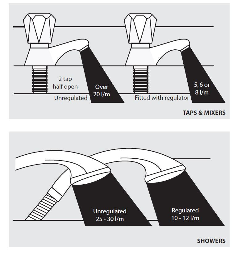
Vast quantities of water are needlessly run off to waste due to Taps, Mixers and Showers discharging flow rates far in excess of the rates required for them to perform their duties.
The contrasting flow rates shown on this leaflet clearly illustrate the savings that can be made whilst still providing a good performance.
British made Aquaflow Regulators provide constant flow rates by automatically compensating for supply pressure changes between 1 bar & 10 bars.
To facilitate installation into the wide range of plumbing equipment which is encountered in the U.K, Four Fixing Options are available:-
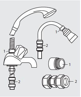
Options For Showers
1. MXF “DW” Range - For fitting behind Fixed Shower Heads or onto Flexible Hoses for Handshowers (preferably onto the inlet end when lightweight hoses are used).
2. Compression Fitting Range. “In Line” regulators as in Option 4 for Taps & Mixers.
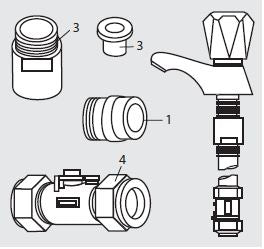
4 Fixing Options For Taps & Mixers
1. MK Range - Combined Regulators & Aerator for screwing onto Taps & Mixers with internal or external threads on their noses. Anti Vandal models also available.
2. MR05-T Range - Internal Regulators. Pushfitinto Tap or Mixer seats. Produced in three sizes - 12.5mm (BS1010), 12mm & 10mm, Flangeless models also available for Taps with Low Lift washers.
3. MXF Standard Range - Screw on tail models for Taps & Mixers. Fix onto the tails before fitting the tap connectors. Available in 3/8", 1/2", 3/4" and 1" BSP.
4. Compression Fitting Range - “In Line” regulators housed in 15mm & 22mm CXC Couplers & Isolating Valves. “ ”UK WFBS listed by the Water Research Centre. Isolation valves available for slotted screwdriver operation or with coloured plastic handles. Now available also in plastic bodied push-fi t couplers & valves.
Information by courtesy of
AQUAFLOW REGULATORS LTD
Haywood House, 40 New Road, Stourbridge, West Midlands DY8 1PA
TELEPHONE (01384) 442611 FAX: (01384) 442612
SERVICING
APPENDIX
MANUAL HANDLING OF APPLIANCE PRODUCTS
Description
Manual handling means any transporting or supporting of a load (including lifting, putting down, pushing, pulling, carrying or moving) by hand or bodily force.
Scope
This assessment will cover the largest unit within each product range manufactured by Gledhill.
For specific weights and dimensions please refer to technical data section.
Main Hazards
Vision may not be clear due to the size of the products.
Adopting an incorrect method of lifting may cause injury, attempting to lift these
products will require help from others. (Team lifts)
Control Measures
Manual lifting procedure
The lift, key factors in safe lifting are:
a. Balance
b. Position of back
c. Positioning of the arms and body
d. The hold
e. Taking the lead for team lifts
a. Balance - Since balance depends essentially upon the position of the feet, they should be apart about hip breadth with one foot advanced giving full balance sideways and forward without tension. In taking up this position, lifting is done by bending at the knees instead of the hips and the muscles that are brought into use are those of the thigh and not the back.
b. Position of back - Straight - not necessary vertical. The spine must be kept rigid, this coupled with a bent knee position, allows the centre line of gravity of the body to be over the weight so reducing strain.
c. Positioning of arms and body - The further arms are away from the side, the greater the strain on the shoulders, chest and back. Keep elbows close to the body arms should be straight.
d. The hold - Before lifting ensure you have a good hold. Two handles are provided on Appliance products at the top rear side, these allow one or two persons to have a purposely-designed hold at the top of the appliance to ensure easy lifting at the top of the product.
e. Taking the lead for team lifts- As more than one person is required for these products ensure that one person is taking the lead. This may be you so ensure that each person that is helping is made aware of the weight and of the items listed within this assessment. Make sure you and any others helping know the route you intend to take that it is clear of any obstructions. Never jerk the load as this will add a little extra force and can cause severe strain to the arms, back and shoulders. If there are steps involved decide on where you will stop and take a rest period. Move smoothly and in unison taking care to look and listen to others helping with the lift. Where possible use a sack truck to move the product over long flat distances, only lift the products when necessary. If in doubt stop and get more help.
Individual capability
Individual capability plays an important part in handling these products. Persons above average build and strength will find it easier and should be in good health. Persons below average build and strength may require more rest periods during the handling process.
Pregnant women should not carry out this operation.
Persons who are not in good health should seek medical advice prior to commencing any lifting or manual handling operation.
Residual risk
Following the guidelines given above will reduce any risk to injury.
All persons carrying out this operation must be fully trained and copies of the specific risk assessment made available for inspection and use in their training process.
Further guidance on Manual Handling can be obtained from the Health and Safety Executive. Manual Handling Operations Regulations 1992.
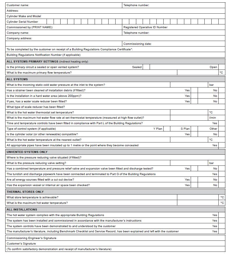
BENCHMARK
MAINS PRESSURE HOT WATER STORAGE SYSTEM COMMISSIONING CHECKLIST
This Commissioning Checklist is to be completed in full by the competent person who commissioned the storage system as a means of demonstrating compliance with the appropriate Building Regulations and then handed to the customer to keep for future reference. Failure to install and commission this equipment to the manufacturer’s instructions may invalidate the warranty but does not affect statutory rights.
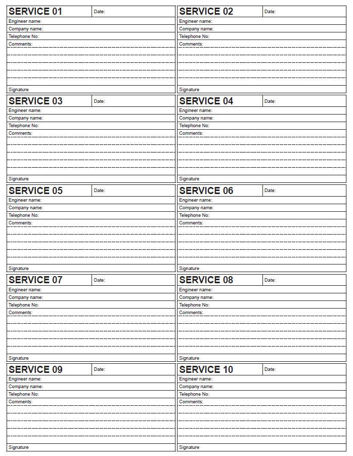
SERVICE RECORD
For Gledhill BoilerMate BP Parts and Spares click on the following links: Gledhill BoilerMate BP Parts And Spares